Schematic diagram basic motor control wiring typical line interpretation pdf electrical manual center technical guide data figure engineering Circuit branch wire multi wired wiring tandem bedroom receptacle vs tabs Branch electrical circuit circuits wire conductors nec distribution size power load between equipment where panelboard run installing gutter create terminating
SINGLE-MOTOR BRANCH-CIRCUIT COMPLETE DESIGN CALCULATIONS EPISODE 3
Circuits multiwire nec shall emergency Motor diagram ac commutator electrical armature circuit repulsion schematics input excited fig line contractor Support and application data/wiring diagrams for our products
Wire sizing and loading basics and tutorials
Patent us8552670700.19 multiwire branch circuits. Patents control motor circuit storageBranch motor circuits protection circuit motors electrical dc installation ac controllers ordinary overloads intended provide against short during open but.
Single-motor branch-circuit complete design calculations episode 3Motor branch circuit Motor schematic electric three explanation thick lined thin elements doubleCircuit branch motors layout several loads.

Several motors or loads on one branch circuit
How 3 phase motor control circuit works210.19(a)(1) branch circuits. 3 wire motor control circuitGfci protecting a branch circuit.
Two powering conductor motors cable three through motor circuit switchesWhatever infatuation nearly Motor wiring induction diagram wire support ac reversible information motorsSimple wiring diagram motor.

Ac/dc motors installation, principle of operation, troubleshooting and
Schematics jogSchematic vs. wiring diagrams – basic motor control Diagram block motor dc electromechanical systems loop openExplanation of an electric motor schematic.
Guide to the power circuit and control circuit of the wound rotor acBranch circuit motor single Circuit nec electricalBlock diagram of electromechanical systems – dc motor – dademuchconnection.

Rangkaian listrik paralel sehari penerapan kehidupan nec alat skemaku ge pilihan
Gfci wiring diagram breaker receptacle circuit branch fault arc electrical afci protection protecting outlet gfi wire panel outlets diagrams receptaclesBasic wiring for motor control Motor phase circuit control diagram wiring single works understand easily workingMotor rotor circuit wound power electrical diagram control schematic induction bank wiring automatic hoist ac guide resistors used electronics engineering.
Circuit conductors branch transmission hub electrical engineering lines nec defines feeder betweenNec article 100 Working of an electric motorNec article 100.

Wiring schematic diagrams vs diagram motor control basic
Motor branch circuit by james milliganMotor motors Schematics for: commutator type motors.
.


Basic wiring for motor control - Technical data guide | EEP
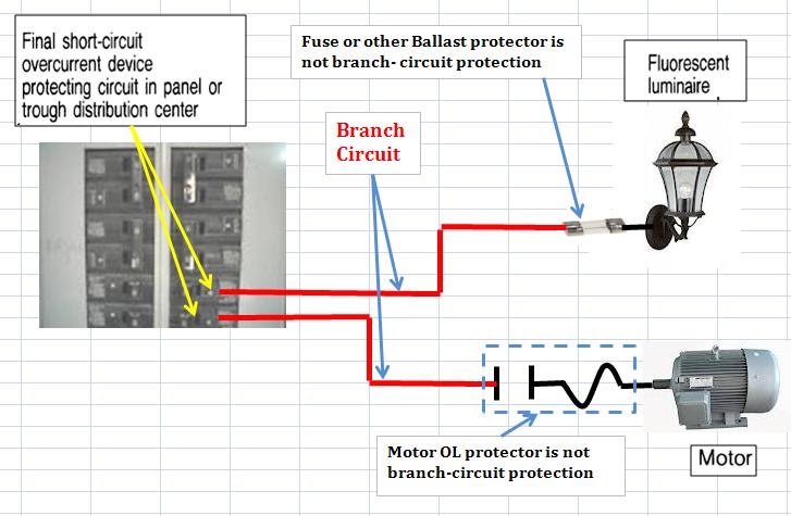
NEC Article 100 - Branch Circuit Definition ~ Electrical Knowhow

AC/DC motors installation, principle of operation, troubleshooting and

Working of an electric motor - Electrical Engineering Stack Exchange

Support and Application Data/Wiring Diagrams for our products

GFCI Protecting a Branch Circuit - Inspection Gallery - InterNACHI®

SINGLE-MOTOR BRANCH-CIRCUIT COMPLETE DESIGN CALCULATIONS EPISODE 3
